Connections MLA-2
The connections for the generation-2 MLA™ are described below. Some generation-2 MLA™ have a clean front side without any BNC connectors, and in that case the necessary connections to the host AFM are contained in a composite AUX connector on the back side of the MLA™.
Front-side connections
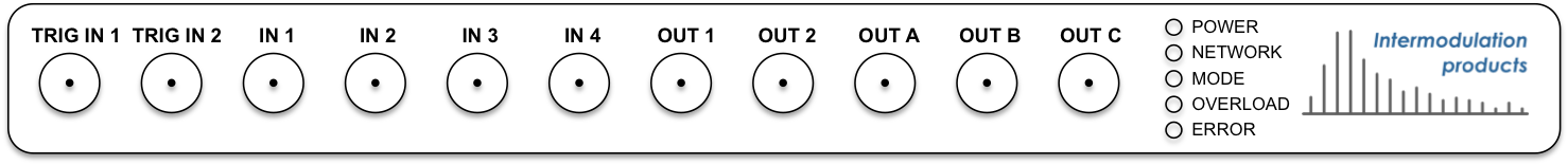
TRIG IN 1andTRIG IN 2are input trigger ports. In a standard configuration these are configured to receive End-of-Line (EOL) and End-of-Frame (EOF) trigger signals respectively.IN 1andIN 2are fast inputs which can operate at a maximum of 250 Msam/sec. The exact speed of these ports can be configured from the software. The frequencies analyzed at these inputs are set by your firmware configuration.IN 3andIN 4operate at a maximum of 62.5 Msam/sec. The exact speed of these ports can be configured from the software. The frequencies analyzed at these inputs are set by your firmware configuration.OUT 1andOUT 2are fast output ports. The user can specify at run-time which drive frequencies are sent to which output ports.OUT A,OUT BandOUT Care three slow output ports run-time controllable by the user, combined speed is 800 kSam/sec. A standard configuration usesOUT Afor AFM feedback.
Back-side connections
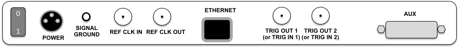
POWERis supplied to the MLA™ via an external power supply. Use only the power supply delivered from Intermodulation Products. Using any other supply voids the warranty.SIGNAL GROUNDgives external access to the grounding point for all input signals.RF CLOCK INandRF CLOCK OUTconnections are used for synchronizing the internal clock of the MLA™ with the clock of some other piece of measurement equipment. They receive and send respectively, a 10MHz square waveform, AC-coupled, voltage range 2 Vpp. Other frequencies and voltage levels can be configured from the software. These ports are designed to connect to a 50 Ohm matching impedance and signal distortions may occur if the receiving or sending connection is not 50 Ohm on the other end.ETHERNETThe MLA™ communicates with the computer via the Ethernet connection. The MLA™ may be directly connected to the Ethernet connection on the computer, or it may be be put behind an Ethernet router, switch or gateway.TRIG OUT 1andTRIG OUT 2send trigger signals from MLA™ to an external device. If your version of the MLA™ does not have front-side connections, these ports will be labeledTRIG IN 1andTRIG IN 2and they receive End-of-Line (EOL) and End-of-Frame (EOF) trigger signals respectively from the host AFM.AUXis used for a composite cable connection and it may be empty if your version of the MLA™ has front-side connections. If your version of the MLA™ does not have front-side connections, this port is used for a composite cable connection to the host AFM. A typical configuration uses an 8-channel DVI connector which connects to a Signal Access Module (SAM), for example for the Bruker Nanoscope V controller (Icon and FastScan SPMs). The DVI cable contains to the necessary input and output ports, which are otherwise accessible on the front-sided connections.